|
Main / Frame synchronizers / PDFE-7309
| PDFE-7309 HD/SD SDIembedded synchronizer with audio input and HDMI auxiliary output |
PROFLEX™ PDFE-7309 series HD/SD SDIembedded synchronizers accept the SD/HD SDI stream to syncronize video to the REF signal (PAL black burst for SD or tri-level for HD), embed up to four audio channels with the "audio follows video delay" capability.
The input audio signal may be in any standard: an analog, AES or combination of both. These modificatiuons are designated the following model indexes:
- four analog balanced inputs (24-bits ADC) – the "AA" index, (f.e. PDFE-7309-AA)
- two analog balanced inputs and one balanced AES/EBU input (4 channels in total) – the "AE" index, (f.e. PDFE-7309-AE)
- two balanced AES/EBU inputs (4 channels) – the "EE" index, (f.e. PDFE-7309-EE)
The PDFE-7309 module occupies two slots in the PROLFEX 1U/3U racks so that two synchronizers fit into a 1U rack and up to seven into a 3U rack.
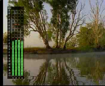
The PDFE-7309 synchronizers are featuring the monitoring HDMI output with the OSD of the bar-graph audio level meters.
PDFE-7309 rear panel:
PDFE-7309 simplified schematic diagram:
PDFE-7309 accepts HD/SD SDIembedded input signals. SDI input is equalized, decoded into a 10-bits 4:2:2 stream which is processed by a frame synchronizer.
The audio streams are delayed to follow the video delay, the audio gain is optionally adjusted. The output HD/SD SDI signal may embed the external audio from analog/AES inputs.
Features:
- HD/SD SDI compliance
- electrical and HDMI outputs are available simultaneously
- automatic cable equalizer on SDI input
- built-in 1kHz test generator
- built-in color bar generator
- signal loss indicator
- EDH/CRC status indicators
- built-in sync gen lock status indication
- manual timing adjustment within the ±99 TV lines range
- automatic detection and indication of an embedded audio in the input SDI signal
- audio delay follows video
- audio channel remapping
- presettable audio gain
- bargraph audio level meter (quazi-peak and UV) OSD on HDMI monitor output
- an analog, AES/EBU or combination of audio inputs
- 24-bits audio ADC
Technical specifications
- Inputs
- SDI
| Standard compliance |
SMPTE 292M (HD SDI) |
50I/1920*1080(2640*1125), 1080I/50 |
59.94I/1920*1080(2200*1125), 1080I/59.94 |
60I/1920*1080(2200*1125), 1080I/60 |
25P/1920*1080(2640*1125), 1080P/25 |
29.97P/1920*1080(2200*1125), 1080P/50 |
30P/1920*1080(2200*1125), 1080P/30 |
50P/1280*720(1980*750), 720P/50 |
59.94I/1280*720(1650*750), 720I/59.94 |
60P/1280*720(1650*750), 720P/59.94 |
| SMPTE 259M (SD SDI) |
50I/720*576, 625I/50 |
59.94I/720*480, 525I/59.94 |
| Input impedance, connector type |
75 Ohm, BNC |
| return loss |
better than 14dB at 1.485GHz |
| Automatic cable equalization |
(Belden 1694A or similar), up to 75m for HD SDI (1.485Gbps) or 300m for SD SDI (270Mbps) |
- Analog AUDIO
| Connector |
DB-15 |
| input impedance |
more than 10kOhm |
| input type |
balanced |
| 0 dB FS level |
+18dB (+24dB jumper-selectable) |
| Dynamic range |
better than 100dB |
| ADC |
24-bits at 48kHz (only 20 MSBs are embedded) |
| Harmonic distortions and noise |
less than 0,006% |
| audio gain presets |
±6dB with 0.2dB steps |
- AES/EBU
| input type |
transformer balanced |
| Connector type |
DB-15 |
| Amplitude |
0.2~4.0V at 110 Ohm |
| audio gain presets |
±6dB |
- REF
| input type |
AC-coupled |
| connector type |
BNC |
| signal type |
for HD SDI |
tri-level |
| for SD SDI |
composite black-burst, 1V p-p |
| input impedance |
more than 10kOhm |
- Outputs
- SDI
| connector type |
BNC |
| number of outputs |
two, reclocked |
| return loss |
better than 12dB at 1.5GHz |
| SDI signal rise and fall times |
270ps (HD SDI), 700ps (SD SDI) |
| jitter |
less than 0.2UI |
| H-timing adjustment |
advance/delay within half TV line with 37ns (SD SDI) or 13,8ns (HD SDI) increments |
| V-timing adjustment |
advance/delay within 99 TV lines with one TV line increments |
| audio gain presets |
±6dB with 0.2dB steps |
- HDMI
| connector type |
miniHDMI |
| standard compliance |
as per input signal standard |
PDFE-7309 controls and indicators:
The MODE button toggles through all the modes, the UP and DOWN buttons edit them.
- INP - input signal format selection
- BARS - built-in color bar generator ON/OFF
- ASSIGN 1/2 EXT/GR/CH - audio channel outputs mapping (selects a group and a channel to be reembedded into a new output group's channels 1 and 2)
- ASSIGN 3/4 EXT/GR/CH - audio channel outputs mapping (selects a group and a channel to be reembedded into a new output group's channels 3 and 4)
- GAIN 1/2 - the audio gain presets in the 1st and 2nd stereo pair or AES signal
- GAIN 3/4 - the audio gain presets in the 3rd and 4th stereo pair or AES signal
- TON - the built-in 1kHz test tone generator ON/OFF
- OUT GROUP - a group number select/disable for a remapped audio
- H/V TIMING - the timing within a TV line/frame relative to the REF signal
- VU METR - the VU-meter controls (ON/OFF, scale type, placement on the screen)
Status indicators:
- EDH/CRC MIN/HOUR - lit if two or more EDH/CRC errors were detected within one hour/minute interval. Both LEDs flash if there is no input video.
- REF UNLOCK - lit if:
- no REF input signal present
- the built-in sync-gen is not locked to the input REF signal
- the input REF signal is not of the same standard as an input HD/SD SDI
- LOSS - lit when SDI input is lost
- BARS - lit when the color bars are being inserted
Configuring the PDFE-7309
The input signal format selection:
Toggling the MODE button select the INP mode. Pressing the UP and DOWN buttons select an input signal standard.
- A## – input signal standard autodetection:
- A62 - standard definition signal (625I/50)
- A52 - standard definition signal (525I/60)
- A80 - high definition signal (1080I/50 or 1080P/25)
- A80. - high definition signal (1080I/60 or 1080P/30 or 1080P/29.97)
- A72 - high definition signal (720P/50)
- A72. - high definition signal (720P/60 or 720P/59.94)
- manually-preselectable standards:
- 625 - only standard definition signal accepted (625I/50)
- 80 I – only high definition signal accepted (1080I/50)
- 720 – only high definition signal accepted (720P/50)
- 525 - only standard definition signal accepted (525I/59.94)
- 80 I. – only high definition signal accepted (1080I/60)
- 720. – only high definition signal accepted (720P/60)
- 80 P – only high definition signal accepted (1080P/25)
- 80 P. – only high definition signal accepted (1080P/30)
- 80.I. – only high definition signal accepted (1080I/59.94)
- 72.0. – only high definition signal accepted (720P/59.94)
- 80.P. – only high definition signal accepted (1080P/29.97)
Built-in color bar generator ON/OFF:
Toggle the BARS button. The built-in color bar generator is disabled/enabled with the standard preselected in the INP configuration step. No input video is required. The 1kHz test-tone or an external audio embedding is possible.
The audio remapping and external audio embedding:
The PDFE-7309 is featuring external audio inputs accepting two analog stereo pairs or two AES signals. The 1st stereo pair or AES signal is considered as "channel A", its' left channels is #1, its' right channel is #2. Therefore the 1st stereo pair is considered as "A1/2", the 2nd stereo pair is called "B1/2" accordingly.
Each SDIembedded audio group consists of four channels (1 to 4) which comprise two channel pairs (1/2 and 3/4). An SDI stream may embed up to four groups, i.e. up to sixteen audio channels.
Toggling the MODE button select the ASSIGN 1/2/EXT/GR (or ASSIGN 3/4/EXT/GR) mode. Pressing the UP and DOWN buttons select an audio source for the 1/2 (or 3/4) channel pair of an output group. The leftmost LED display would announce the selected source:
- A - the 1/2 (or 3/4) channel pair of the output group will contain the A external stereo pair
- B - the 1/2 (or 3/4) channel pair of the output group will contain the B external stereo pair
- 1, 2, 3, 4 - the 1/2 (or 3/4) channel pair of the output group will contain the stereo pair deembedded from an input SDI signal. (Only available if an input SDI contains valid embedded audio)
Pressing the MODE button again select the ASSIGN 1/2 CH (or ASSIGN 3/4 CH) mode. Pressing the UP and DOWN buttons select the audio channel numbers from the previously selected audio source. The most significant digit on the LED display shows the group number, the two least significant ones display the channels' numbers:
#1/2, #2/1, #1/1, #2/2, #3/4, #4/3, #3/3, #4/4, where # denotes the group number.
An allocation example:
|
indication |
channel # of an output group |
A12 |
A21 |
... |
B12 |
.. |
B22 |
1 |
LEFT channel from external A pair |
RIGHT channel from external A pair |
... |
LEFT channel from external B pair |
... |
RIGHT channel from external B pair |
2 |
RIGHT channel from external A pair |
LEFT channel from external A pair |
... |
RIGHT channel from external B pair |
... |
RIGHT channel from external B pair |
... |
112 |
121 |
134 |
... |
312 |
434 |
1 |
1st channel from the 1st group |
2nd channel from the 1st group |
3rd channel from the 1st group |
... |
1st channel from the 3rd group |
3rd channel from the 4th group |
2 |
2nd channel from the 1st group |
1st channel from the 1st group |
4th channel from the 1st group |
... |
2nd channel from the 3rd group |
4th channel from the 4th group |
The remapper simplified schematics:
The audio gain presets:
Toggling the MODE button select the GAIN 1/2 (or GAIN 3/4) mode. Pressing the UP and DOWN buttons select gain for the channel pair. The audio gain range: ±6dB in 0.2dB increments. The simultaneous depression of the UP and DOWN buttons resets the gain to 0dB.
- #.# – a channel has positive gain of #.#dB
- — #.# – a channel has negative gain of #.#dB
The 1kHz test tone operation:
Toggling the MODE button select the TON mode. Pressing the UP and DOWN buttons select a channel to insert the 1kHz signal into.
- OF - the test signal is OFF in all channels
- On - the test signal is ON in all channels
- 01, 02, 12, 03, 04, 34 - the test signal appears in respective channel(s)
A remapped output audio group number selection:
Toggling the MODE button select the OUT GROUP mode. Pressing the UP and DOWN buttons select an audio group number to embed the channels currently assigned for A and B outputs.
- ban - a new group is neither composed nor embedded
- 1 - the channels currently assigned for A and B outputs are embedded in the 1st group
- 2 - the channels currently assigned for A and B outputs are embedded in the 2nd group
- 3 - the channels currently assigned for A and B outputs are embedded in the 3rd group
- 4 - the channels currently assigned for A and B outputs are embedded in the 4th group
A group number conflict is possible if a new group is assigned the same number that is already present in an input SDI. The main LED indicator will show the nA# in the NEW GROUP mode, where # is the actual clashing number. To resolve the conflict either assign another new group number, or use the ANC STRIP mode to erase the clashing group from the input SDI stream.
The H/V timing adjustments:
Toggling the MODE button select the H/V TIMING mode. The MSD on the main display shows the V (vertical) timing adjustment mode. Pressing the UP or DOWN buttons edit the advance/delay within a TV frame:
- V00 - the output SDI is synchronous with the REF's TV frame
- V.99 ... V.01 - the output SDI advances the REF signal, the V.99 is the maximum advance value - minus 99 TV lines
- V01 ... V99 - the output SDI trails the REF signal, the V99 is the maximum delay value - plus 99 TV lines
Pressing the MODE button once more select the H timing mode. Pressing the UP or DOWN buttons edit the advance/delay within a TV line, the main LED shows three digits:
- 000 - the output SDI is synchronous with the REF's TV line
- 001...### - the output SDI is delayed against the REF signal with 37ns (SD SDI) or 13.8ns (HD SDI) increments, where ### is the maximum allowed delay (the three MSD are displayed only):
- 172 - for 625i/50
- 171 - for 525i/59.94
- 263 - for 1080i/50 and 1080p/25
- 221 - for 1080i/59.94, 1080i/60, 1080p/30 and 1080p/29.94
- 164 - for 720p/59.94 and 720p/60
- 197 - for 720p/50
Because of this display truncation it takes 10 pixels to change the displayed value.
A short depression of the UP or DOWN buttons corresponds to one pixel delay/advance change, a long depression corresponds to five-pixel jumps.
Selecting the VU METR modes:
Toggling the MODE button select the VU METR mode. Pressing the UP and DOWN buttons adjust the horizontal position of the VU-meter OSD. Pressing the MODE and DOWN buttons simultaneously switches the OSD off (the indicator shows "On" -> "OF"). Pressing the MODE and UP buttons simultaneously selects the VU-meter scale mode:
- EBU scale, 0dBfs corresponds to +18 dBU (indicator shows "FS")
- quazi-analog scale, 0dBU corresponds to 0,775VRMS (indicator shows "db")
The remote control and management from a PC
All the PROFLEX™ modules are remote controllable from a PC. This facility is available if a rack is fitted with a CPU module (ordered separately).
|