|
|
Main / SDI embedders and deembedders / PEMB-7108
PEMB-7108 HD/SD SDI video, audio and RS-232 data embedders with HDMI monitor output |
PROFLEX™ PEMB-7108 series HD/SD SDI embedders accept up to four audio channels and one RS-232 data signal to embed into the SD/HD SDI stream.
The PEMB-7108 module occupies one slot in the PROLFEX 1U/3U racks so that up to four embedders fit into a 1U rack and up to fifteen into a 3U rack.
The input and output audio signal may be in any standard: an analog, AES or combination of both. These modificatiuons are designated the following model indexes:
- four analog balanced inputs (24-bits ADC) – the "AA" index, (f.e. PEMB-7108-4AA)
- two analog balanced inputs and one balanced AES/EBU input (4 channels in total) – the "AE" index, (f.e. PEMB-7108-4AE)
- two balanced AES/EBU inputs (4 channels) – the "EE" index, (f.e. PEMB-7108-4EE)
The PEMB-7108 embedders are featuring the monitoring HDMI output with the OSD of the bar-graph audio level meters (quasi-peak and VU).

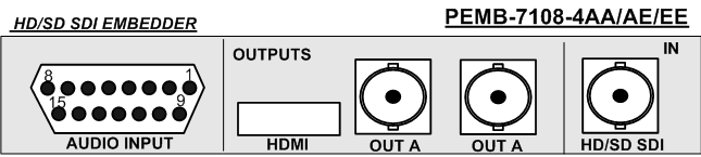
PEMB-7108 rear panel:
PEMB-7108 simplified schematic diagram:
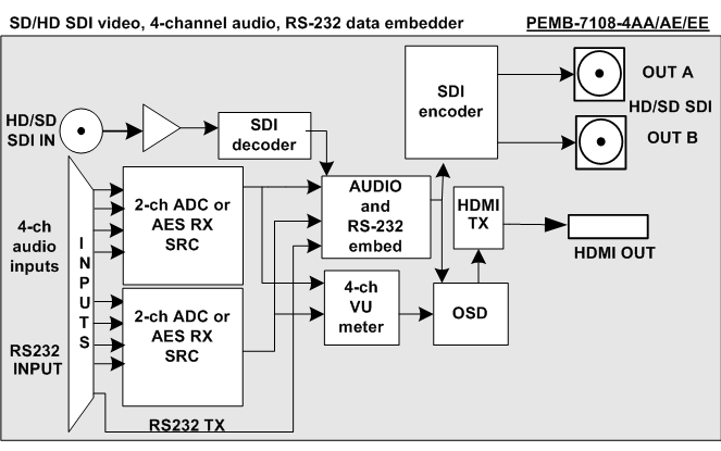
PEMB-7108 accepts HD/SD SDI input signals. SDI input is equalized, decoded into a 10-bits 4:2:2 stream which is processed by a video/audio processor.
The video/audio processor embedds the audio and RS-232 data streams. Input audio may be an analog ("AA" model index), digital AES/EBU ("EE" model index) or combination of both formats ("AE" model index).
Features:
- HD/SD SDI compliance
- electrical and HDMI outputs are available simultaneously
- automatic cable equalizer on SDI input
- built-in 1kHz test generator
- built-in color bar generator
- signal loss indicator
- EDH/CRC status indicators
- automatic detection and indication of an embedded audio in input SDI signal
- audio group selection for embedding
- audio channel mapping
- audio group and ancillary data stripping/editing capability
- presettable audio gain
- cascadability to allow for embedding of more than four audio groups
- bargraph audio level meter (quazi-peak and UV) OSD on HDMI monitor output
- RS-232 support up to 150kbps
- compatibility with a single-signal, WDM and CWDM optical systems
- an analog, AES/EBU or combination of audio inputs
- 24-bits audio ADC
Technical specifications
- Inputs
- SDI
| Standard compliance |
SMPTE 292M (HD SDI) |
50I/1920*1080(2640*1125), 1080I/50 |
59.94I/1920*1080(2200*1125), 1080I/59.94 |
60I/1920*1080(2200*1125), 1080I/60 |
25P/1920*1080(2640*1125), 1080P/25 |
29.97P/1920*1080(2200*1125), 1080P/50 |
30P/1920*1080(2200*1125), 1080P/30 |
50P/1280*720(1980*750), 720P/50 |
59.94I/1280*720(1650*750), 720I/59.94 |
60P/1280*720(1650*750), 720P/59.94 |
| SMPTE 259M (SD SDI) |
50I/720*576, 625I/50 |
59.94I/720*480, 525I/59.94 |
| Input impedance, connector type |
75 Ohm, BNC |
| return loss |
better than 14dB at 1.485GHz |
| Automatic cable equalization |
(Belden 1694A or similar), up to 75m for HD SDI (1.485Gbps) or 300m for SD SDI (270Mbps) |
- Analog AUDIO
| Connector |
DB-15 |
| Input impedance |
10 kOhm |
| Input type |
balanced |
| 0 dB FS level |
+18dB (+24dB jumper-selectable) |
| Dynamic range |
better than 100dB |
| ADC |
24-bits at 48kHz (20 MSB are embedded) |
| Harmonic distortions and noise |
less than 0,006% |
| audio gain presets |
±6dB |
- AES/EBU
| Input type |
transformer balanced |
| Connector type |
DB-15 |
| Amplitude |
0.2~4.0V |
| Input impedance |
110 Ohm |
| audio gain presets |
±6dB |
| Maximum input cable length |
up to 100 m of twisted pair |
- Outputs
- HDMI
| standard compliance |
as per input signal standard |
PEMB-7108 controls and indicators:
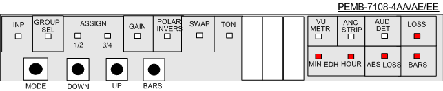
The MODE button toggles through all the modes, the UP and DOWN buttons edit them.
- VIDEO MODE - input signal format selection and the built-in color bar generator enable/disable, TX mode in no-signal condition
- BARS - built-in color bar generator ON/OFF
- GROUP SEL - the audio group selection for the embedding
- ASSIGN - audio channel mapping
- GAIN - the audio gain presets in a selected stereo pair or AES signal
- POLAR INVERS - the polarity invertion in a selected stereo pair or AES signal
- SWAP - left-right swap in a selected stereo pair or AES signal
- TON - the built-in 1kHz test tone generator ON/OFF
- VU METR - the VU-meter controls (ON/OFF, scale type, placement on the screen)
- ANC STRIP - ancillary data stripping ON/OFF
- AUD DET - lit when an input SDI has the embedded audio
- EDH MIN/HOUR - lit if two or more EDH errors were detected within one hour/minute interval
- AES LOSS - lit when AES inputs are selected but at least one of them has no input signal
- LOSS - lit when SDI input is lost
Configuring the PEMB-7108 embedder
The input signal format selection:
Toggling the MODE button select the INP mode. Pressing the UP and DOWN buttons select an input signal standard.
- A## – input signal standard autodetection:
- A62 - standard definition signal (625I/50)
- A52 - standard definition signal (525I/60)
- A80 - high definition signal (1080I/50 or 1080P/25)
- A80. - high definition signal (1080I/60 or 1080P/30 or 1080P/29.97)
- A72 - high definition signal (720P/50)
- A72. - high definition signal (720P/60 or 720P/59.94)
- manually-preselectable standards:
- 625 - only standard definition signal accepted (625I/50)
- 80 I – only high definition signal accepted (1080I/50)
- 720 – only high definition signal accepted (720P/50)
- 525 - only standard definition signal accepted (525I/59.94)
- 80 I. – only high definition signal accepted (1080I/60)
- 720. – only high definition signal accepted (720P/60)
- 80 P – only high definition signal accepted (1080P/25)
- 80 P. – only high definition signal accepted (1080P/30)
- 80.I. – only high definition signal accepted (1080I/59.94)
- 72.0. – only high definition signal accepted (720P/59.94)
- 80.P. – only high definition signal accepted (1080P/29.97)
Built-in color bar generator ON/OFF:
Toggle the BARS button. The built-in color bar generator is disabled/enabled with the standard preselected in the INP configuration step. No input video is required. The 1kHz test-tone or an external audio embedding is possible.
The audio group number selection:
Toggling the MODE button select the GROUP SEL mode. Pressing the UP and DOWN buttons select an audio group number (1, 2, 3 and 4 groups are available).
ATTENTION!
If there is an embedded audio in an input SDI, only the free group numbers will be available for selection. For example, if SDIembedded input has the first group audio, only the 2, 3 and 4 will be cycled through. It is advisable to select the nearest higher number, i.e. the 02 group. If you select a currently available group number and later the same group appears at the SDI input - the indicator notifies about the conflict: for example, the nA1 is shown (group 1 not available). The POTM-7205 stops to embed it's audio and the input SDIembedded audio group is passed through. You should either select any other group or use the ANC STRIP mode to erase the input SDI from any preembedded audio data.
Audio channel (re)mapping within a selected group:
A simplified schematic of the remapper circuitry:
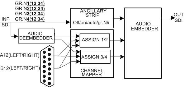
Toggling the MODE button select the ASSIGN 1/2 (or ASSIGN 3/4) mode. Pressing the UP and DOWN buttons select the physical audio channel to be sent in a channel pair 1/2 (or 3/4 respectively). The list of possible labels: A12, A21, A11, A22, B12, B21, B11, B22.
For example:
channel mapping |
A12 |
A21 |
... |
B12 |
... |
B22 |
1 |
A, left |
A, right |
... |
B, left |
... |
B, right |
2 |
A, right |
A, left |
... |
B, right |
... |
B, right |
In case of SDIembedded input signal with audio in four groups numbered from 1 to 4, it is possible re-map and re-allocate both the SDIembedded signals and the external audio channels. Toggling the MODE button select the ASSIGN 1/2 (or ASSIGN 3/4) mode. Pressing the UP and DOWN buttons select the SDI channel pair 1/2 (or 3/4 respectively) from the actually available in the SDI stream. The list of possible labels: 112, 121, 134, 143, 212, 221, 234, 243, 312, 321, 334, 343, 412, 421, 434, 443.
For example:
channel mapping |
112 |
121 |
134 |
... |
312 |
... |
434 |
1 |
1st group, 1st channel |
1st group, 2nd channel |
1st group, 3rd channel |
|
3rd group, 1st channel |
|
4th group, 3rd channel |
2 |
1st group, 2nd channel |
1st group, 1st channel |
1st group, 4th channel |
|
3rd group, 2nd channel |
|
4th group, 4th channel |
A blinking first digit, corresponding to a group number, means that there is no such group in the input SDI stream, the "silence" audio signal will be embedded in this case.
The audio gain presets:
Toggling the MODE button select the GAIN mode. Pressing the UP and DOWN buttons select gain for the 1/2 channel pair. Press the MODE button again to access the 3/4 channel pair and make presets there. The audio gain range: ±6dB in 0.2dB increments. The simultaneous depression of the UP and DOWN buttons resets the gain to 0dB.
- A#.# – the channel A has positive gain #.#dB
- A.#.# – the channel A has negative gain #.#dB
- B#.# – the channel B has positive gain #.#dB
- B.#.# – the channel B has negative gain #.#dB
The audio channel polarity invertion ON/OFF:
Toggling the MODE button select the POLAR INVERS mode. The list of channels an their invertion status is displayed as you press the MODE button:
- 1OF - first channel invertion OFF
- 2OF - second channel invertion OFF
- 3OF - third channel invertion OFF
- 4OF - fourth channel invertion OFF
Pressing the UP and DOWN buttons enable/disable the invertion for the selected channel.
The audio channel LEFT/RIGHT swap:
Toggling the MODE button select the SWAP mode. The list of channels an their L/R status is displayed as you press the MODE button:
- A12 - first channel pair L/R status
- B12 - second channel pair L/R status
Pressing the UP and DOWN buttons enable/disable the LEFT/RIGHT allocation for the selected channel pair (A12, A21, B12, B22).
The 1kHz test tone operation:
- OF - the test signal is OFF in all channels
- On - the test signal is ON in all channels
- 01, 02, 12, 03, 04, 34 - the test signal appears in a selected channel(s)
Selecting the VU METR modes:
Toggling the MODE button select the METR mode. Pressing the UP and DOWN buttons adjust the horizontal position of the VU-meter OSD. Pressing the MODE and DOWN buttons simultaneously switches the OSD off (the indicator shows "On" -> "OF"). Pressing the MODE and UP buttons simultaneously selects the VU-meter scale mode:
- EBU scale, 0dBfs corresponds to +18 dBU (indicator shows "FS")
- quazi-analog scale, 0dBU corresponds to 0,775VRMS (indicator shows "db")
The ancillary data stripping:
In the case of a conflict between a selected audio group number and an input SDIembedded stream one may resolve it by stripping the input SDI signal. Toggling the MODE button select the ANC STRIP mode.Pressing the UP or DOWN buttons enable the stripping mode.
- ANC STRIP OF - the ancillary data stripping is OFF
- ANC STRIP On - the ancillary data stripping is ON
- ANC STRIP AU# - the automatic ancillary data stripping mode: the group number preselected in the GROUP SEL is replaced by the audio being embedded by POTM-7205 optical transmitter. The display shows the actual group number:
- ANC STRIP 1 - the group number 1 is erased fron the input SDI signal
- ANC STRIP 2 - the group number 2 is erased fron the input SDI signal
- ANC STRIP 3 - the group number 3 is erased fron the input SDI signal
- ANC STRIP 4 - the group number 4 is erased fron the input SDI signal
The remote control and management from a PC
All the PROFLEX™ modules are remote controllable from a PC. This facility is available if a rack is fitted with a CPU module (ordered separately).
|